


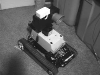
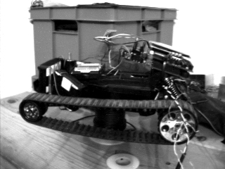
Here you can see the white camera, and conical lense hood of the IR pyroelectric sensor on the pan/tilt head. The pan (stepper)/tilt (servo) mechanism is partially obscured.
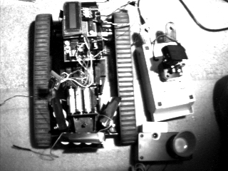
You can see the main power batteries arranged in a triangular configuration. The SRAM backup power is supplied by 4x1.2VDC NiCd batteries located in the center of the triangle. Video system power is supplied by a 12 volt battery pack on the underside of the robot.
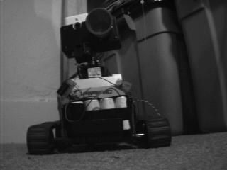
At the rear of the robot are two BNC connectors. The one closest to the camera is for the video transmitter (not mounted yet), and the antenna mounted farther away from the camera is for the radio modem (currently mounted under the upper shell).
4-4-97 I was having a few problems with the servo->sensor array linkage. The joint didn't appear to be strong enough to support the full weight of the sensor array, but I fixed it! I hacked apart an old printer to find a very specific part. It originally housed two gears that meshed together within a metal 'U'. Three hours of cutting and machining with my Dremel tool and it was in place. I can finally continue mounting the sensor array! I have decided to mount the sensor array to the pan-tilt mechanism with 'carpet tape' for safety reasons. After all, I don't want the entire thing to snap off if it hits something.
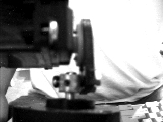 Before
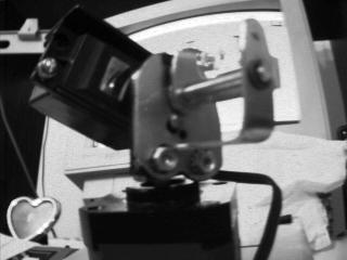 After
After
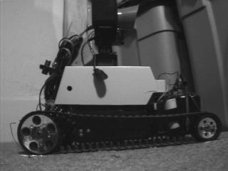
Here you can clearly see the old weak servo/stepper link, and the secure, yet kludgely looking support fixture. It only looks bad, it's really quite strong.
Last update 3-16-1998