The Matrix

20x20 Audio Video Matrix Switch


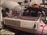
Several years ago I acquired a TiltRac #7030-02 20x20 A/V matrix switch board from a local surplus dealer during their going out of business sale. I was unable to find additional information about the board's original purpose, or sufficient detail of how it worked so was left with only one recourse: reverse engineering. Fortunately, the board uses discreet components, so it wasn't all that difficult to figure out.


Detailed Hardware Analysis

The board consists of 21 cascaded MC14094 8-bit serial shift registers, each one addressing five 74HC4052 analog multiplexers giving access to all 20 of the paired A/V inputs. The 21st channel has a video blanking interval circuit to detect the presence of a video signal. A SIP header is provided for access to the Strobe, Data, Clock and Video Sense I/O lines as well as Vcc and ground. Each audio output is buffered with a high-impedance input unity gain buffer, and the video input is terminated with a 75 ohm resistor and normalized. With this design, any of the inputs can be switched to one or more of the outputs. The only disadvantage is that there is only one audio channel per input, so inputs and outputs must be doubled-up for stereo.

Each channels' MC14094 is connected to the five 74HC4052s as follows:
Q1- NC
Q2- Enable(17-20)
Q3- Enable(13-16)
Q4- Enable(9-12)
Q5- Enable(5-8)
Q6- Enable(1-4)
Q7- S1
Q8- S2

Since the S1 and S2 address selection lines are shared by each channel, only one Enable line should be asserted at a time (active low).

The 74HC4052s are attached to the inputs fairly logically:

Channel
       Input
     0      
1
5
9
13
17
     1
2
6
10
14
18
     2
3
7
11
15
19
     3
4
8
12
16
20


Hardware Design

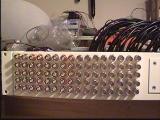
The 11 inch height of the PCB wasn't well suited to effective use of space on a 19 inch rack and the RCA connectors were a bit flimsy, so I decided to use a 2U rack mount case and extend the A/V to the front with panel mount BNC connectors. To keep the software design simple, and the costs down I decided to use an extra Basic Stamp 1 I had available to interface with the board. Power comes from a fused 5V 3A switching power supply.


Software Design

The memory limitations of the Stamp 1 do not allow for storing all of the matrix settings at the same time, so the controlling computer must keep track of this for us. The technique used to shift the bits out of the BS1 requires that they be sent LSB->MSB which complicates the conversion process a little, but leaves the upper case ASCII range available for use as control characters.

In order to allow easier debugging, and an option for higher-speed communication the BS1 allows for two methods of communication: character and binary modes. Character mode allows for the matrix channel settings to be submitted as the ASCII-equivalent of a decimal number which is converted by the BS1. Binary mode allows a single binary value to be submitted for each channel. Two other control commands are allowed at any point during communication: Latch and Video Detect. Latch pulses the MC14094's latch lines to update the shift registers output allowing for a partial matrix load when needed. Video Detect measures the pulse width of the video detect output. If the timer expires before detecting a state transition it is determined that there is no video present on the input. This status information is returned to the host computer via the serial port.

ASCII character
Decimal
Function
V
86
check if video present on channel 21
B
66
binary mode
C
67
character mode
L
76
latch outputs

In either Binary or Character modes, the Stamp receives the matrix channel settings from 21->1 then latches the outputs and returns the status of the video detection circuit. This is unless the 'L' control character is received before receiving the last channel setting, at which time matrix channel loading is terminated and the Latch line strobed.

Each output can correspond to any one of the inputs:

Input
Decimal
ASCII
1
120
x
2
121
y
3
122
z
4
123
{
5
116
t
6
117
u
7
118
v
8
119
w
9
108
l
10
109
m
Input
Decimal
ASCII
11
110
n
12
111
o
13
92
\
14
93
]
15
94
^
16
95
_
17
60
<
18
61
=
19
62
>
20
63
?


The code running on the Matrix' BS1 is here.


Host Computer Software Interface

Since I'm using The Matrix with my existing MisterHouse HA setup I needed to write a module to support it. To ease in the association between inputs and outputs, text aliases are provided via the config file. The current code consists of two files: Matrix.pm, which must be intalled in mh/lib/, and matrix.pl which goes in the user's code directory. The module handles low level communication with the device and includes subroutines for sending channel settings and scanning the inputs for video. The user code file creates the nescessary Voice_Cmds and manages the web page icons dependant on the video input status.


Construction

Front
BNC
RG59
BS1


Last update 12-19-2002

Back